Menu
latest blog
Lorem ipsum dolor sit amet, consectetur adipiscing elit. Ut elit tellus, luctus nec ullamcorper mattis, pulvinar dapibus leo.

Aluminum PCB: The Ultimate Guide to Metal Core Thermal Management
In the rapidly evolving world of electronics, heat is the silent killer. As components shrink and power densities rise—driven by High-Power LEDs, Electric Vehicle (EV) inverters, and fast-charging stations—traditional circuit boards can no longer cope with the thermal load. Enter the Aluminum PCB, the industry’s most robust solution for thermal management.
But what exactly is an Aluminum PCB? Is it just a standard board glued to a piece of metal? How does it achieve thermal conductivity ten to twenty times higher than standard FR-4?
This comprehensive guide will deconstruct the Aluminum PCB (also known as Metal Core PCB, MCPCB, or IMS). We will explore its unique anatomy, the chemical engineering behind its dielectric layers, manufacturing challenges, and why Credisyn’s CS-AL Series is the material of choice for engineers demanding reliability under heat.
1. Defining the Aluminum PCB: More Than Just Metal
At its core, an Aluminum PCB is a type of Metal Core Printed Circuit Board (MCPCB). Unlike standard FR-4 boards, which rely on woven glass and epoxy for structural support, an Aluminum PCB uses a metal substrate to dissipate heat away from critical components.
Technically referred to as IMS (Insulated Metal Substrate), this technology acts as a “thermal bridge.” It efficiently transfers heat from the component (heat source), through a specialized dielectric layer, to the metal base, and finally to a heatsink or the ambient air.
The Anatomy of an Aluminum PCB
To understand its performance, we must dissect its three-layer structure. This is where Credisyn’s manufacturing expertise differentiates a standard board from a high-performance solution.
A. The Circuit Layer (Conductive Copper)
The top layer is the copper foil where the electrical circuit is etched.
- Thickness: Ranging from 1oz (35μm) to 10oz (350μm) for high-current applications like EV Battery Management Systems (BMS).
- Current Capacity: Because the aluminum base dissipates heat so effectively, a trace on an Aluminum PCB can carry significantly higher current than the same trace on FR-4 without overheating.
- Credisyn Specifics: We utilize Electro-Deposited (ED) copper with specific grain structures to ensure high peel strength (>1.2 N/mm) even after thermal cycling.
B. The Dielectric Layer (The “Secret Sauce”)
This is the most critical layer. It must be electrically insulating (to prevent short circuits) but thermally conductive (to move heat). This is a paradox in physics, as most good insulators (like plastic) are also thermal insulators.
- The Credisyn Innovation: Standard dielectrics offer 0.5–1.0 W/m·k. Credisyn’s CS-AL Series utilizes a proprietary resin formulation filled with nano-ceramics, such as Alumina (Al2O3) and Boron Nitride (BN).
- Performance: These fillers create a “thermal highway” while blocking electron flow. This allows us to achieve thermal conductivity ratings from 1.0 W/m·k up to 8.0 W/m·k.
- Breakdown Voltage: The layer is typically 50μm to 150μm thick. Despite its thinness, it must withstand high voltages. Credisyn’s dielectric offers a breakdown voltage (Hi-Pot) of 3000V to >6000V AC, crucial for automotive power inverters.
C. The Base Layer (The Aluminum Substrate)
The bottom layer provides mechanical strength and the bulk of the thermal mass.
- Alloy 1050/1060: Standard aluminum. Good thermal conductivity (~220 W/m·k) but softer.
- Alloy 5052: Credisyn’s preferred choice for automotive applications. It has higher tensile strength and better vibration resistance.
- Alloy 6061: A magnesium-silicon alloy used for structural components where the PCB serves as part of the device chassis.
2. The Physics of Thermal Management: How It Works
Why switch from FR-4 to Aluminum? The answer lies in Thermal Resistance (Rth).
In a standard FR-4 board, the base material is epoxy and glass.
- FR-4 Thermal Conductivity: ~0.25 to 0.3 W/m·k.
- Result: Heat gets trapped under the component. The Junction Temperature (Tj) rises rapidly. For every 10°C rise in Tj above the limit, the lifespan of an LED or semiconductor is cut by 50%.
In a Credisyn Aluminum PCB:
- Dielectric Thermal Conductivity: 2.0 W/m·k to 8.0 W/m·k.
- Mechanism: Heat is generated at the LED junction. It passes through the solder joint to the copper circuit. Instead of hitting a thermal wall (FR-4), it flows instantly through the nano-ceramic dielectric into the aluminum base. The aluminum spreads the heat over a large surface area (spreading resistance), allowing it to dissipate into the air or a heatsink.
The Result: A matrix LED headlight running on a Credisyn CS-AL-4000 board operates 15°C to 20°C cooler than on a standard MCPCB, significantly extending its operational life.
3. Types of Aluminum PCBs
While the Single-Sided IMS is the most common, the technology has evolved into several complex variations to suit different design needs.
A. Single-Layer IMS
The workhorse of the industry.
- Structure: Circuit / Dielectric / Aluminum Base.
- Application: Streetlights, General Lighting, Power Converters.
- Cost: Most economical.
B. Double-Sided Aluminum PCB
This allows for more complex routing but introduces manufacturing challenges.
- Structure: Circuit / Dielectric / Circuit / Dielectric / Aluminum Base.
- Complexity: You cannot drill through the aluminum to plate a via (it would short to the base). Therefore, blind vias are used to connect the two copper layers before laminating to the base.
- Use Case: High-density power supplies where component space is limited.
C. Hybrid Aluminum PCB
A fusion of FR-4 and Metal Core.
- Structure: A standard FR-4 board is processed separately and then bonded to an aluminum base using a thermal adhesive.
- Benefit: Allows for complex multilayer routing (4+ layers) with the thermal benefits of a metal heat spreader.
- Credisyn Note: We supply specific “Pre-Bond” materials optimized for this lamination process to ensure no delamination occurs during reflow.
D. Flexible Aluminum PCB
Uses specialized aluminum alloys (like 5754) and flexible dielectrics (Polyimide-based).
- Benefit: The board can be bent or formed into 3D shapes during assembly (though not continuously flexed like a ribbon cable).
- Application: Automotive headlights that wrap around the corner of the vehicle vehicle chassis.
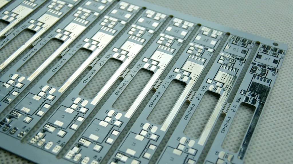
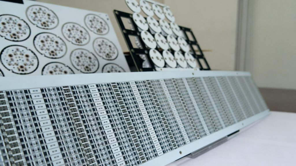
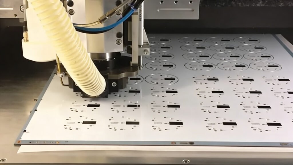
4. Manufacturing Process: The Credisyn Way
Manufacturing an Aluminum PCB is fundamentally different from FR-4 processing. It requires heavy-duty machinery and precise chemical controls. Here is a look inside the Credisyn factory floor.
Step 1: Surface Treatment (Anodizing)
Raw aluminum readily oxidizes. To ensure the resin sticks to the metal, Credisyn performs a specific anodizing or micro-etching process on the aluminum surface. This increases the surface area at a microscopic level, ensuring a mechanical bond that resists delamination.
Step 2: High-Pressure Lamination
We combine the Copper Foil, the Ceramic-Filled Resin (Prepreg), and the Aluminum Plate.
- Press Cycle: Unlike FR-4 which cures at ~170°C, high-performance IMS often requires vacuum pressing at elevated temperatures to fully cure the ceramic resin without voids.
- Void-Free: Any air bubble in the dielectric is a potential electrical failure point (Hi-Pot failure). Credisyn uses vacuum lamination to ensure 100% void-free dielectrics.
Step 3: Drilling and Routing
- Tool Wear: Aluminum is soft but “gummy.” It generates heat when drilled. Standard drill bits clog and break. We use specialized carbide tools with optimized flute geometries to clear chips effectively.
- Burr Control: Drilling aluminum creates sharp metal burrs. If not removed, these burrs can puncture the dielectric and cause a short. We employ a rigorous de-burring and planarization process.
Step 4: Solder Mask and Surface Finish
The white solder mask seen on LED boards is not just for aesthetics; it is highly reflective. Credisyn uses specific “Super-White” inks that resist yellowing under high heat (260°C reflow) and high UV exposure, maintaining reflectivity >90% for the life of the product. Common surface finishes include HASL (Hot Air Solder Leveling) and OSP (Organic Solderability Preservative).
5. Key Advantages of Aluminum PCBs
Why are engineers shifting their designs to Credisyn CS-AL materials?
1. Superior Thermal Dissipation
This is the primary driver. With thermal conductivity up to 8.0 W/m·k, these boards allow engineers to run components at higher currents or eliminate bulky cooling fans, reducing the overall system size.
2. Dimensional Stability
Aluminum is much more stable than FR-4. As the board heats up, FR-4 expands significantly, stressing the solder joints. Aluminum expands, but at a predictable and lower rate, especially in the X/Y axis.
- Credisyn Spec: Our CS-AL series maintains dimensional stability of < 2.5%, ensuring consistent alignment for large arrays of LEDs.
3. Mechanical Strength and Durability
Ceramic substrates (Alumina/Aluminum Nitride) are brittle and can crack under torque (e.g., screwing the board down). Aluminum is ductile and tough. It withstands vibration and shock, making it ideal for automotive environments where boards are subjected to constant road vibration.
4. EMI Shielding
The aluminum base acts as a massive ground plane. It provides natural shielding against Electromagnetic Interference (EMI), which is crucial for power electronics switching at high frequencies.
5. Environmental Sustainability
Aluminum is 100% recyclable. Unlike FR-4, which is a composite waste product at the end of its life, the aluminum base can be reclaimed. Credisyn also promotes Halogen-Free manufacturing in our CS-HF aluminum series.
6. Applications and Case Studies
The versatility of Aluminum PCBs has seen them adopted across multiple high-growth industries.
Case Study A: Smart City LED Lighting
The Challenge: A municipal client needed a streetlight solution that could last 50,000 hours in outdoor environments ranging from -20°C to +50°C. The Credisyn Solution: We supplied CS-AL-2000 (2.0 W/m·k).
- Why: The 2.0 W/m·k conductivity kept the LED junction temperature below 85°C even on hot summer nights.
- Result: The failure rate dropped to <0.1% over 5 years, saving the city millions in maintenance costs.
Case Study B: Automotive Matrix Headlights
The Challenge: A Tier-1 automotive supplier needed a PCB for a high-intensity Matrix LED headlight. The board had to fit a curved housing and withstand engine vibration. The Credisyn Solution: We utilized CS-AL-4000 (Alloy 5052).
- Why: Alloy 5052 provided the necessary tensile strength for the mounting points. The 4.0 W/m·k dielectric handled the intense heat flux of the high-current LEDs.
- Result: The headlight design passed all automotive vibration and thermal shock tests (1000 cycles).
Case Study C: EV On-Board Charger (OBC)
The Challenge: An EV manufacturer required a power conversion board capable of handling 400V. The Credisyn Solution: High-Voltage Aluminum PCB.
- Why: We used a 150μm dielectric thickness with a Hi-Pot rating of >5000V AC. We used 4oz heavy copper to handle the charging current.
- Result: Safe, efficient power conversion with rapid heat dissipation to the liquid cooling plate.
7. Comparison: Aluminum vs. FR-4 vs. Copper Base
To help you select the right material, here is a direct comparison.
Feature
Standard FR-4
Credisyn Aluminum PCB
Copper Base PCB
Thermal Conductivity
0.25 - 0.3 W/m·k
1.0 - 8.0 W/m·k
10.0 - 400 W/m·k
Cost
Low
Medium
High (Variable)
Rigidity
Flexible/Rigid
Rigid / Strong
Rigid / Heavy
Machinability
Excellent
Difficult (Burrs)
Very Difficult
Shielding
None
Good
Excellent
Application
Logic, Signal
LED, Power, Auto
High-End RF, Mil-Spec
Why not always use Copper Base? While Copper Base PCBs offer superior thermal performance (Copper conducts heat at ~400 W/m·k vs Aluminum at ~220 W/m·k), they are significantly heavier and more expensive. Aluminum represents the “Sweet Spot” of price-to-performance for 90% of commercial applications.
8. Design Guidelines for Aluminum PCBs
Designing for metal core requires a shift in mindset compared to FR-4.
A. Copper Trace Width
Because the aluminum base sucks heat away so fast, soldering can be difficult (the iron heat dissipates instantly).
- Tip: Use thermal relief pads for manual soldering.
- Heavy Copper: If using >3oz copper, ensure the trace width and spacing (space/trace) is adequate for etching. Credisyn recommends a minimum of 0.2mm spacing for heavy copper to prevent shorts.
B. Single Layer Routing
Remember, in a standard IMS, you only have one layer for routing. You cannot use vias to jump over traces.
- Tip: Use 0 Ohm resistors as “jumpers” if necessary, or optimize component placement to untangle the “rats nest” of connections.
C. Solder Mask Definition
White solder mask reflects light but can show discoloration if the reflow profile is too hot.
- Tip: Follow Credisyn’s recommended reflow profile (Peak 245°C – 260°C) to maintain the pure white aesthetic required for lighting applications.
9. Future Trends: The Credisyn Roadmap
The demand for Aluminum PCBs is growing in parallel with the Green Energy revolution. Credisyn is actively researching the next generation of materials.
- Ultra-High Thermal Conductivity: We are testing Nano-Carbon and Diamond-dust fillers to push dielectric conductivity beyond 10 W/m·k to rival expensive ceramic substrates.
- Bendable Metal Dielectrics: Developing resin systems that are flexible enough to allow for tighter bend radii in automotive housing without cracking the dielectric insulation.
- Direct Thermal Path (DTP): Advancing technology where the LED thermal pad is soldered directly to the metal base (eliminating the dielectric layer under the heat pad) for zero thermal resistance.
Conclusion: Partnering for Thermal Excellence
The Aluminum PCB is no longer a niche product; it is the backbone of the LED lighting industry and the enabler of the Electric Vehicle revolution. It solves the fundamental problem of modern electronics: Heat.
However, not all Aluminum PCBs are created equal. The difference lies in the Dielectric Chemistry and the Manufacturing Precision. A cheap aluminum board with voids in the dielectric or poor bonding strength is a liability waiting to fail.
At Credisyn, we do not just manufacture boards; we engineer thermal solutions. From our Class 1000 Cleanrooms ensuring contaminate-free dielectrics to our ISO 14001 and IATF 16949 certified quality systems, we provide the reliability that global brands trust.
Whether you are designing a Smart City streetlight or a next-gen EV inverter, choosing the right material is the first step toward success. Explore the Credisyn CS-AL Series today and let us help you keep your electronics cool, efficient, and reliable.
Frequently Asked Questions (FAQ)
Q: Can I use standard FR-4 components on an Aluminum PCB? A: Yes, standard Surface Mount Devices (SMD) work perfectly. However, Through-Hole components are difficult to use because the metal base is conductive. You cannot easily pass a lead through the aluminum without insulating it, which is complex and costly.
Q: What is the maximum voltage an Aluminum PCB can handle? A: This depends on the dielectric thickness. A standard 100μm dielectric can usually withstand roughly 3000V AC breakdown. Credisyn offers High-Voltage options (High-CTI) that exceed 5000V-6000V for automotive and industrial power applications.
Q: Why is the thermal conductivity of the dielectric more important than the aluminum? A: The aluminum base is a great conductor (220 W/m·k), but the heat must first pass through the dielectric layer. If the dielectric is poor (e.g., 0.3 W/m·k), it acts as a “bottleneck.” Credisyn focuses on high-performance dielectrics (2.0 – 8.0 W/m·k) to open up this bottleneck.
Q: Is Aluminum PCB more expensive than FR-4? A: Generally, yes, it is slightly more expensive due to the cost of the aluminum plate and specialized manufacturing. However, it often eliminates the need for external heatsinks, fans, and heat paste, often making the total system cost lower.
Q: What is the “Peel Strength” of Credisyn Aluminum PCBs? A: Peel strength measures how strongly the copper foil sticks to the dielectric. Credisyn ensures a peel strength of >1.2 N/mm (Newtons per millimeter), ensuring traces do not lift off even under high heat or physical stress.
Paper core copper-clad substrate
Glass cloth copper-clad substrate
Cloth paper composite copper-clad substrate
Cloth felt composite copper-clad substrate
Paper core copper-clad substrate
Glass cloth copper-clad substrate
Cloth paper composite copper-clad substrate
Cloth felt composite copper-clad substrate
Credisyn quality copper clad laminates for global electronics
Credisyn-Professional CCL manufacturer, delivering reliable electronic substrate solutions worldwide.
Quick Link
Email: info@credisyn.com
Quick Link
Add: No. 18 Hong Kong Middle Road, Qingdao, China
Copyright © 2025 Website Title Copper Cladd Laminated Supported by Credisyn technology